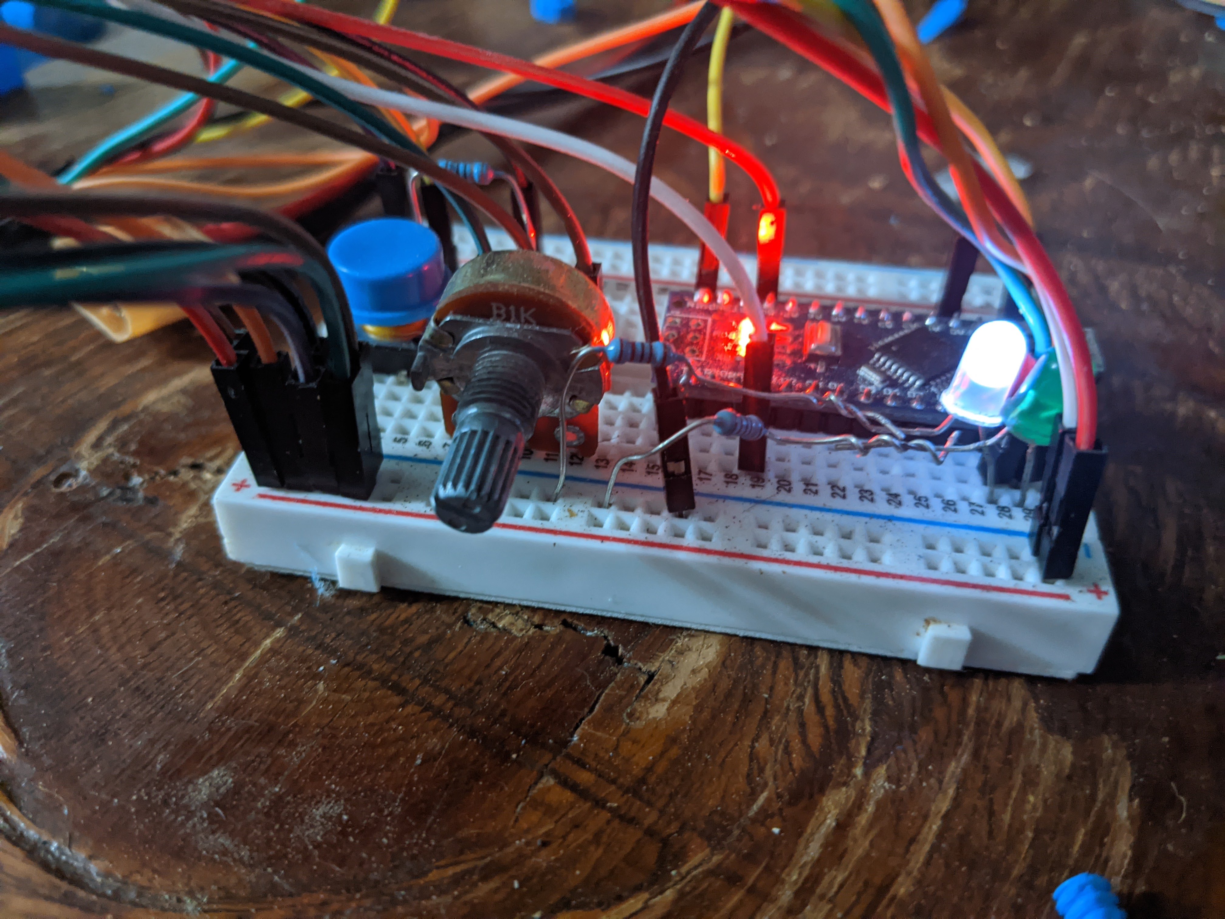
Arduino Nano
This project was inspired by my cat Tommy. The idea came to me while I was at the store trying to pick out a new cat toy. I thought of many variations of toys with laser pointers and strings, but I decided that the main focus would be a single spinning axle that a toy would be attached to. I would consider this my 3rd big project which is based around a microcontroller which means that I had a good deal of experience in some areas starting off. Over the years I have gained experience with using various sensors and modules so I knew that working with those wouldn't cause too many problems. I knew that I wanted to base a project around 3d printed gears, but I had to learn to design my own parts to be 3d printed which was one of the main challenges going into this project.
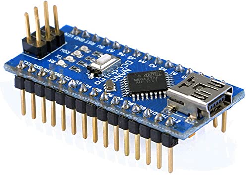
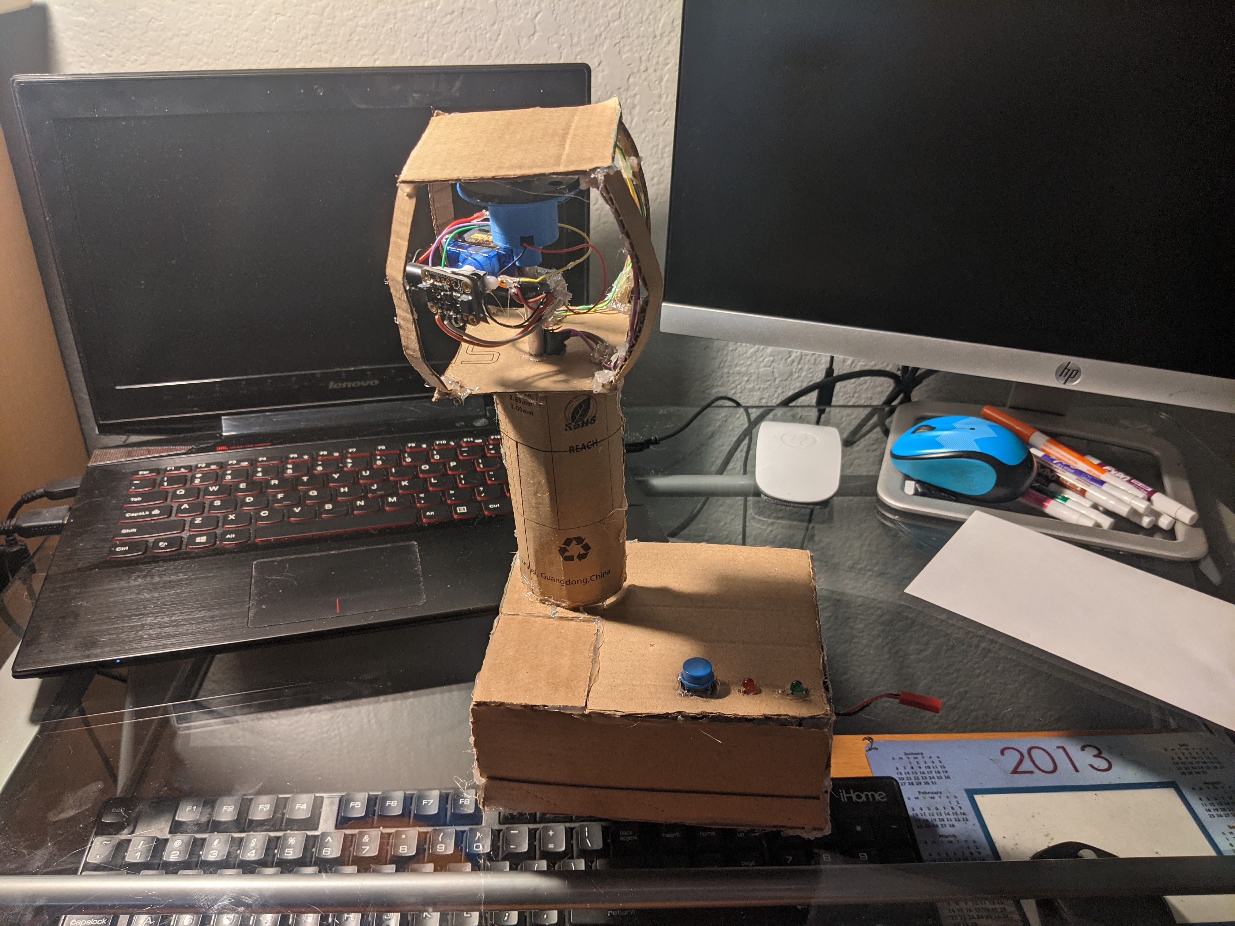
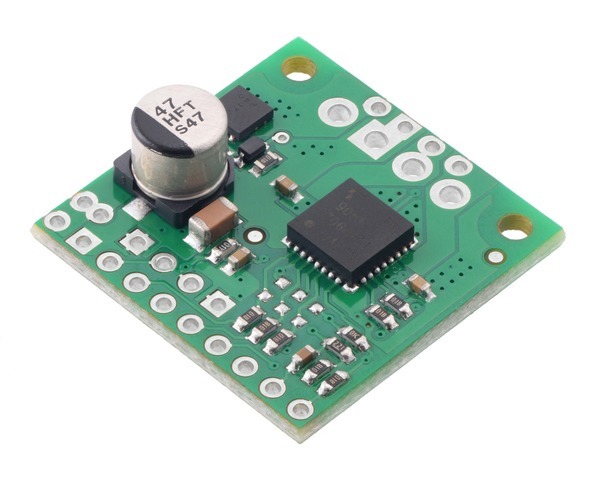
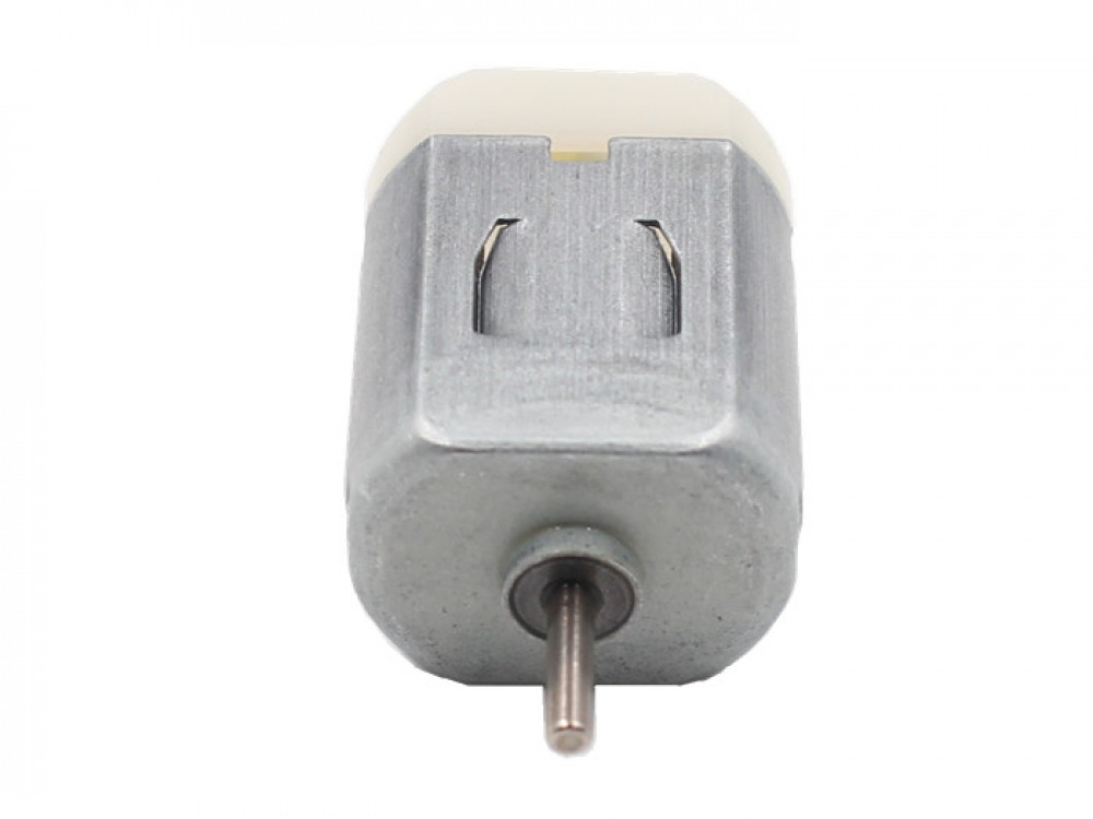
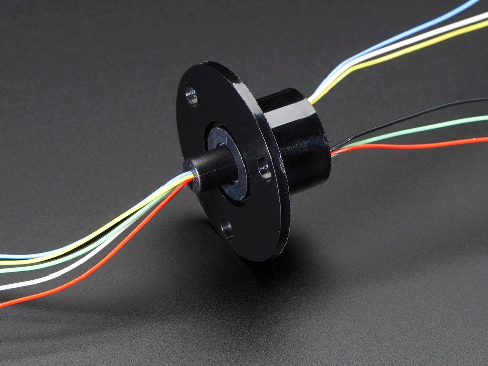
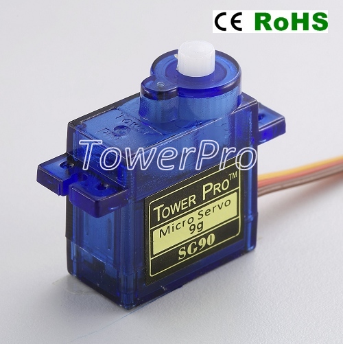
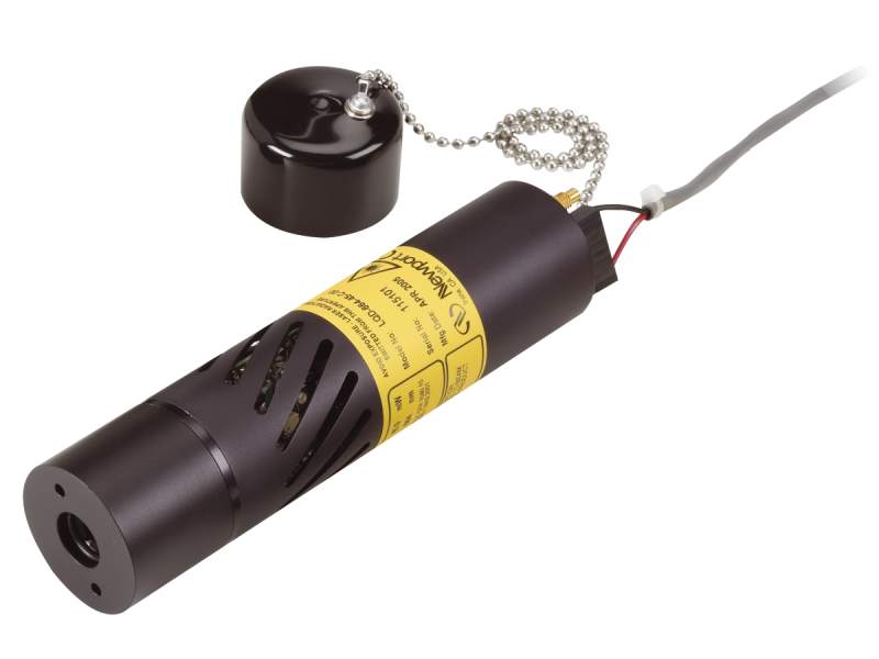
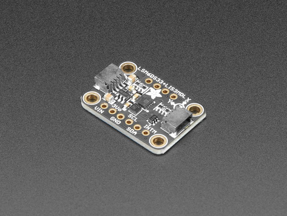
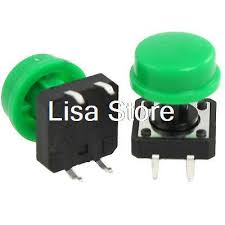
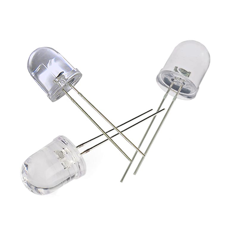
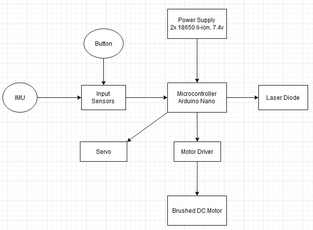
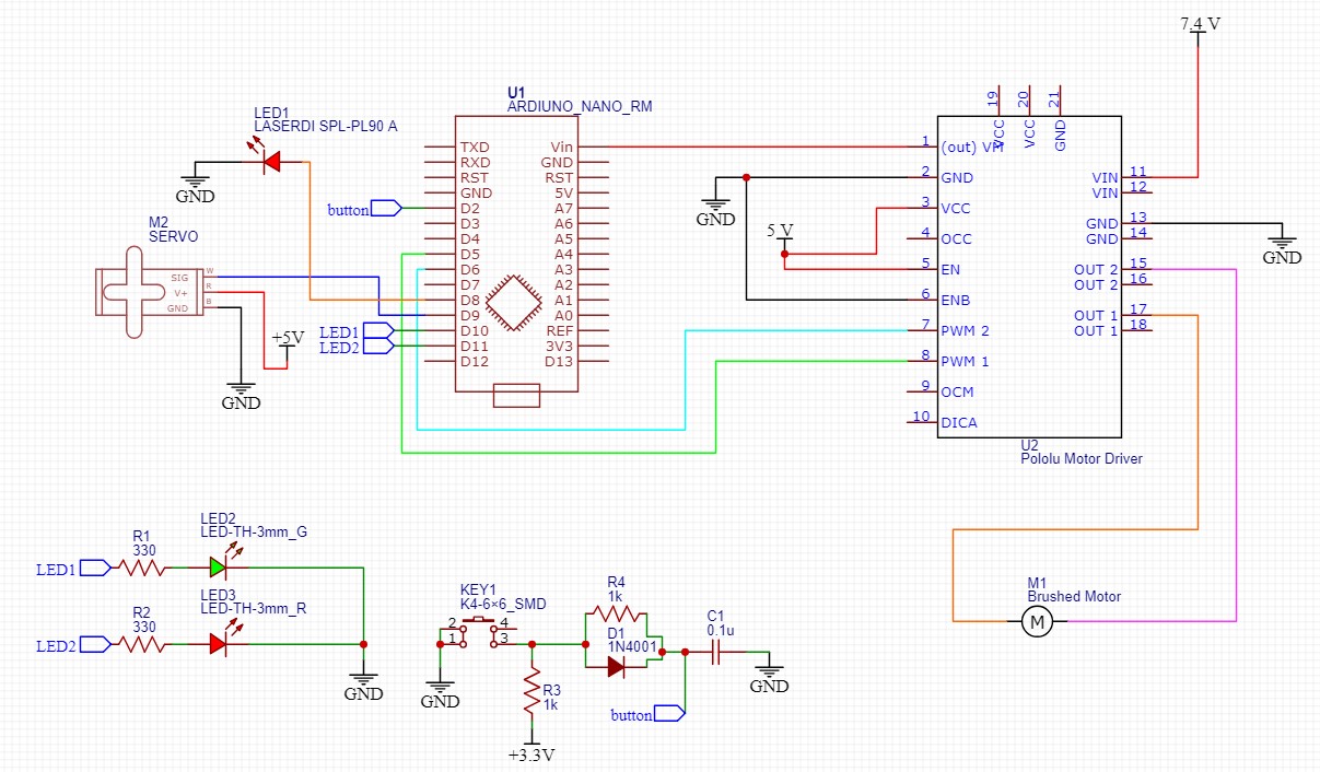
The device that I have constructed is meant to be used as a cat toy. The toy's frame is made from various pieces of cardboard held together by hot glue. It has an axle shooting upwards from the base that spins with the help of a gear reduction powered by a toy dc brushed motor. The brains of the project is an Arduino Nano which is used to drive the motor through a seperate motor driver breakout. The electronics at the top of the spinning shaft which are a servo motor, a laser diode, and an IMU all take instructions from the Arduino. These electronics use a slip ring to avoid getting tangled by the spinning shaft. The Arduino allows me to coordinate movement and sensor data in order to create any pre-programmed paths that I want. I can use the Arduino's internal timer to alternate the direction of the servo and dc motor. All of the electronics are powered by a 2s LI-ION battery pack. I also added a button and a few indicator LEDs to allow greater ease of use. I usually write button debouncing in the software, but this time I created a debouncing circuit using some, resistors, a capacitor, and a diode.
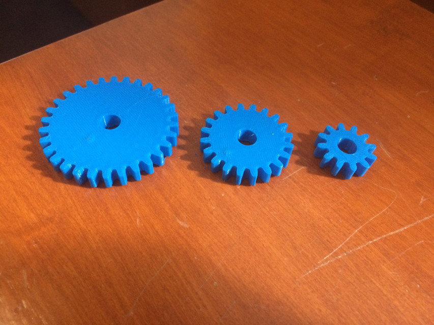
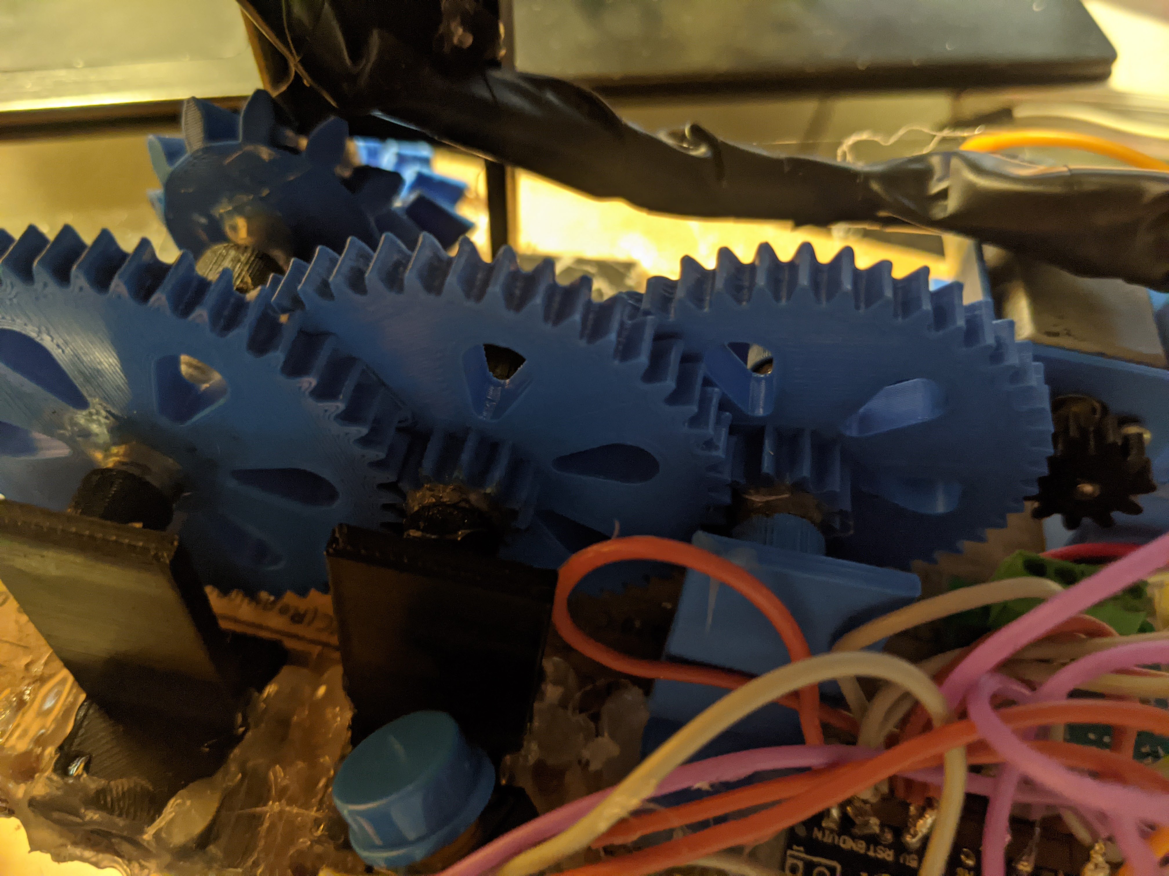
Before starting this project, I created several prototype gear systems in order to test my first 3d printed gears. I mainly held all of the axles down with hot glue which led to many problems because the axles were not held down strongly enough. Because the frame of the device is made out of cardboard I felt as though my options were limited. To adress this I redesigned my 3d printed parts to be thicker to better withstand the forces of the gears. I also epoxied some pieces that were especially troubling. I found that running the motor at a high speed increases the chances of a piece unsticking, so I try to use lower voltages.